A UMI gripper that matches the robot it collects for
A UMI variant for the I2RT YAM arm. It matches the handheld gripper’s embodiment to YAM’s stock linear gripper — jaw geometry, camera mount, tips, and the rail-and-pinion mechanism that synchronizes both jaws — to minimize the distribution shift between data collection and deployment. No servo encoder, no brittle lever linkage. Inspired by HandUMI, which took the hand-worn approach from Generalist.
Hardware post, not a results post: it is built and the tracker is measured, but no policy has been trained on its data yet. Files: github.com/YosubShin/yam-umi.
0. The thing in one picture
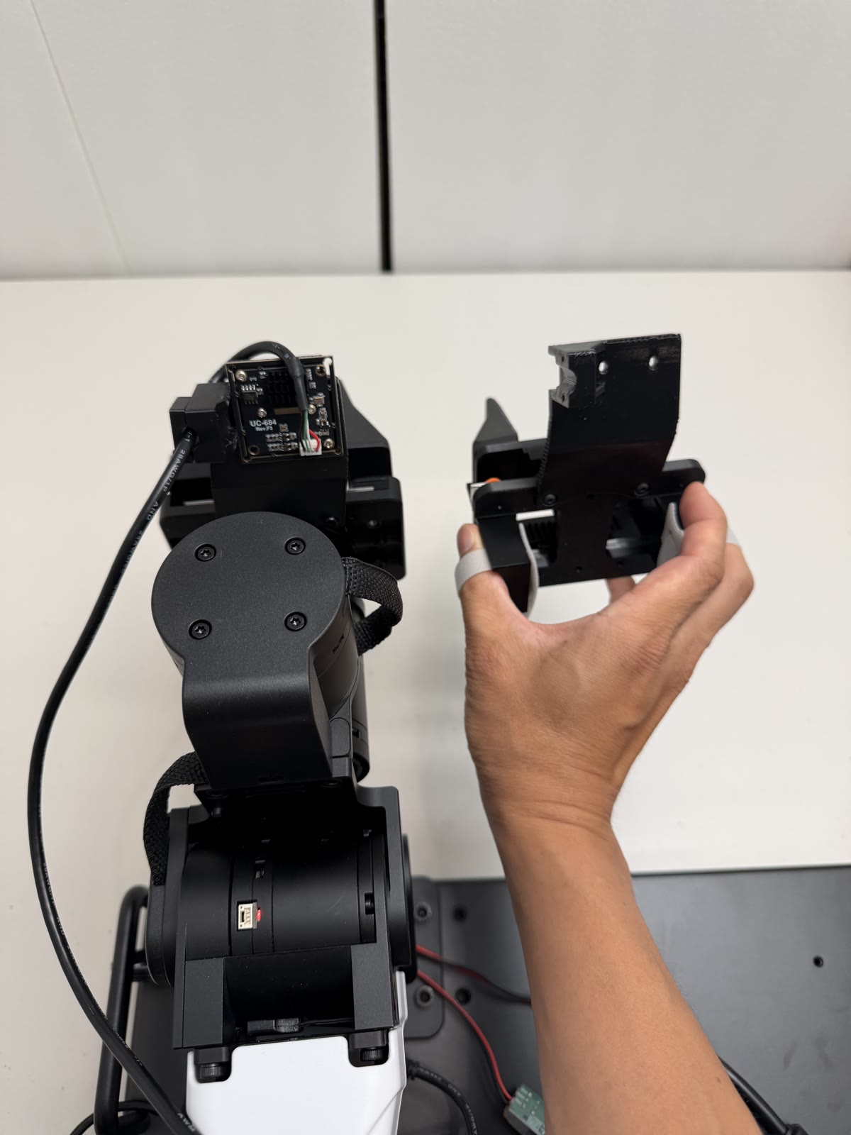
Left is the I2RT YAM arm’s linear gripper. Right is a handheld device that copies it: same jaw geometry, same wrist camera mount, and the same gripper tips — literally the spare set that ships with the arm. You wear it, you demonstrate a task, and the wrist camera records roughly what the robot’s wrist camera would have recorded doing the same thing.
1. Why bother — direction of adaptation
A UMI-style rig exists so you can collect demonstrations without a robot in the loop. The policy you train from that data consumes wrist-camera images, so the whole approach rests on one assumption: that what the camera sees while a human demonstrates resembles what it sees while the robot executes.
That is not my observation — it is UMI’s own design principle, stated plainly in the paper: “When deploying UMI on a robot, we place GoPro cameras with the same location with respect to the same 3D-printed fingers as on the hand-held gripper.” They call it minimizing the observation embodiment gap, and report that wrist-camera video is “almost indistinguishable” between demonstration and deployment. Anyone building in this space is working downstream of that idea, this project included.
What differs between designs is the direction in which the match is achieved.
UMI adapts the robot to the interface. You bolt UMI’s 3D-printed fingers and a GoPro onto whatever arm you have, and the parity follows. This is exactly what makes UMI hardware-agnostic — any arm with a parallel jaw stroke over 85 mm qualifies, and they demonstrate the same policy on a UR5e and a Franka. Fast-UMI takes the same direction, pairing the handheld device with a robot-mounted counterpart to hold the observation perspective consistent.
YAM-UMI adapts the interface to the robot. The arm keeps its stock gripper tips and its stock camera mount; the handheld device is what changes to match.
That direction is worth choosing when the deployment side is the part you don’t want to touch — a fleet already standardized on one arm, a configuration you’ve already validated, gripper tips the manufacturer supplies. You give up generality completely: this fits a YAM linear gripper and nothing else. In exchange nothing about the robot changes, and the collection rig inherits the deployment geometry rather than the other way round.
2. Where this started: trying to use HandUMI
I did not set out to design a gripper. I set out to use HandUMI, which is one of the few open hand-worn UMI designs whose linkage keeps the two jaws synchronized — moving together the way a parallel gripper does, rather than independently following your two fingers. For anyone targeting a linear gripper that property is the hard part, and HandUMI has it. It was the obvious starting point.
Two things stopped it working on a YAM.
The camera extrinsic couldn’t be matched. HandUMI sits in a third position on section 1’s axis: rather than adapting either side, it keeps one shared body across arms and swaps only the gripper tips, leaving the rest to software retargeting. That is a reasonable design — it is what lets one rig serve an AgileX Piper, an ARX X5, a Trossen WidowX and others — but it means the camera sits where the shared body allows, and its mount doesn’t readily adjust to reproduce the YAM camera’s angle relative to the tips.
The lever linkage broke. Its printed lever parts popped out of the mechanism under normal use. The load path runs through printed plastic links, and that’s where it failed for me.
If you want a robot-agnostic rig, or a direct encoder reading of aperture, HandUMI is still the better choice and you should use it. I needed neither of those things and needed the camera pose, so I built something narrower.
3. The mechanism is the robot’s mechanism
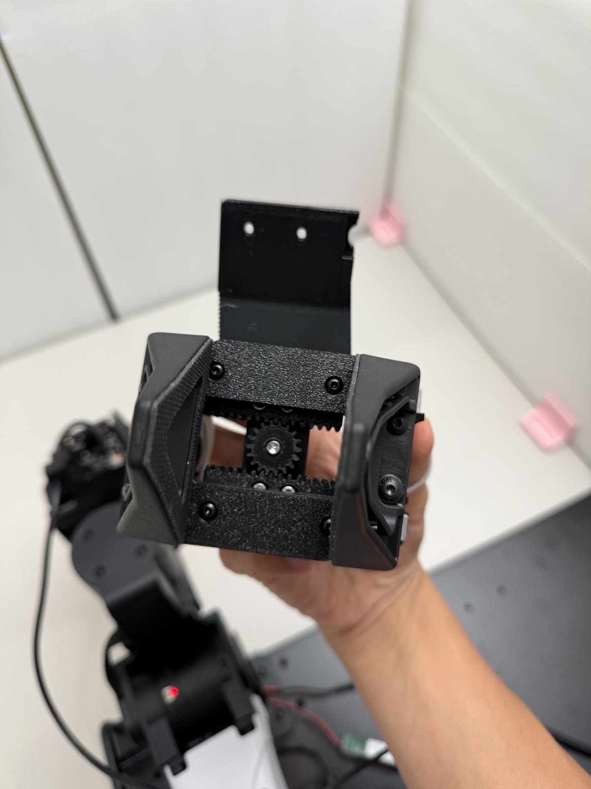
Two MGN9 linear rails, one per jaw, with a rack on each and a single pinion between them. A one-handed pinch drives both jaws symmetrically.
The reason this is worth a section: this is what’s inside the YAM gripper. Two MGN9 rails, two racks, a pinion. It isn’t an alternative to HandUMI’s crank linkage that I preferred on the merits — it’s convergence on the robot’s own design.
So the parity isn’t only optical and geometric, it’s kinematic. The jaws travel the way the robot’s jaws travel, aperture is symmetric about the same centreline, and the relationship between your pinch and the resulting width is one the robot can actually execute. There’s no mechanism-level retargeting between collection and deployment because there’s no mechanism difference to retarget.
A practical note that cost me several prints: the pinion’s fit against
the racks is not predictable from CAD. Printer, filament and the
squareness of the heat-set inserts all move it. The repo ships four
pinion variants at 0.1 mm steps of outside diameter — print all four on
one plate and keep whichever runs smoothest. Mine was v3; yours may
not be.
4. No servo
HandUMI reads aperture from a Feetech servo encoder. That gives a clean per-frame width signal, and you pay for it by backdriving the servo through its gear train on every single pinch — adding friction to the one motion the device exists to record faithfully.
YAM-UMI goes back to what the original UMI did and reads aperture from ArUco markers on the tips. What that buys:
- No backdrive friction. The pinch is the rails and the rack-and-pinion, nothing else.
- No servo, controller, or power supply in the BOM, and no cable routing for them.
- No lever linkage in the load path — the printed parts are brackets and mounts.
This is not a novel idea. It’s the original UMI’s approach, and I’m returning to it rather than inventing anything.
5. Wrist pose: SLAM by default, markers if you can afford a camera
The default way to get SE(3) wrist pose here is camera SLAM from the wrist fisheye — the original UMI approach. It needs nothing from the repo beyond the camera and mount, and it keeps collection portable, which is the point of a handheld rig.
I also had a dodecahedral ArUco marker ball from another project, and it mounts to this gripper. If your setup can host a fixed external camera, it’s more precise:
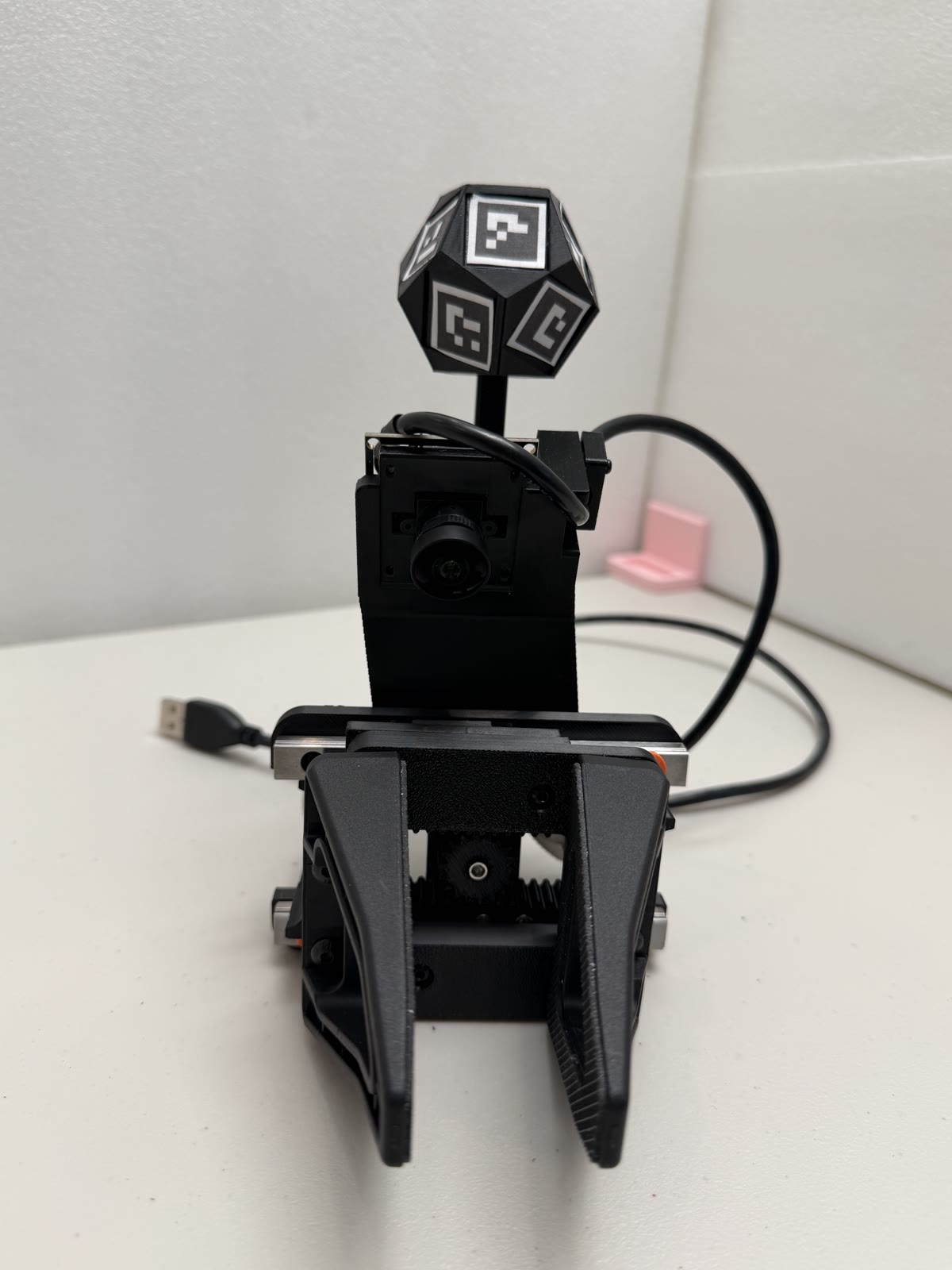
Measured at ~94 cm standoff, on settled holds:
| Metric | Result |
|---|---|
| Within-hold precision | 0.46 mm RMS (median), p90 0.68 mm |
| Revisit repeatability | 0.08–0.17 mm SD per axis |
Coverage — the fraction of frames with enough faces visible to solve a bundle pose — depends heavily on the external camera:
| Camera | ≥1 face | ≥2 faces | ≥3 faces |
|---|---|---|---|
| Sony (4K 30p, H.264) | 100% | 90.8% | 77.5% |
| Arducam B0591 (1080p) | 79.6% | 68.3% | 59.1% |
Two caveats travel with those numbers and I don’t want them read without them. First, settled holds only — dynamic tracking isn’t certified, so 0.46 mm is not a moving-arm figure, which is of course the case that matters for data collection. Second, relative, not absolute — precision and relative motion are trustworthy, but absolute pose in the robot frame isn’t resolved. A camera-versus-forward-kinematics comparison showed median 14% scale and 9° direction discrepancies. I suspect FK, lever-arm or extrinsics error rather than the camera, but I haven’t run it down, so I’m not making an absolute world-frame claim.
There’s also no VR-controller mount. It would be easy to add and I haven’t.
6. What this doesn’t show yet
In the spirit of the rest of this site, the honest list:
- No end-to-end result. I haven’t collected a dataset with this and trained a policy on it. The camera-parity claim is by construction — it has not been validated against recorded imagery, which is the obvious next thing to do and the only thing that would actually prove the argument in section 1.
- Aperture accuracy is unmeasured. Fiducial width against the YAM encoder, or against calipers over a swept aperture, would be the single most valuable number to add. Notably it’s also the number that would answer the strongest objection to dropping the servo.
- The tracker calibration solver isn’t published. The markers go on the dodecahedron in any arrangement and the layout is recovered by a bundle solve, which means my numbers above are readable but not yet reproducible by anyone else.
- One arm, forever. No support for other grippers is planned. That’s the trade from section 1, and it isn’t a soft one.
7. Cost and files
About $79 per gripper in parts — two MGN9 rails and carriages, two bearings, two hook-and-loop straps, and a $57 fisheye camera, which is most of it. Shop supplies (filament, fastener kits, heat-set inserts, tape) are listed separately and not counted, on the theory that anyone printing this already owns them. The gripper tips are free if you own the arm, because spares ship with it.
Design files, BOM, and assembly notes: github.com/YosubShin/yam-umi — STEP and STL, MIT licensed.
Built on the shoulders of UMI (Chi et al.), HandUMI, and I2RT’s own published YAM CAD. Not affiliated with I2RT.